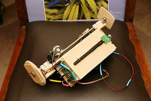
Test platform for Burning Man Project.
Combine basic functional elements into structured system.
| Swarm Bot |
|
|
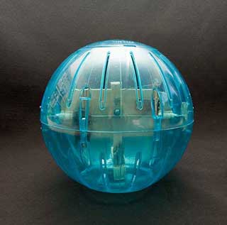
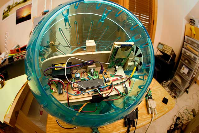
First used with R/C to proto-type rolling ball drive and steering system.
Now being used as platform to test modular sensor/control system.
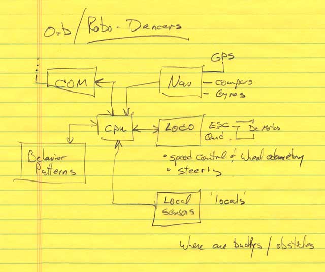
By breaking up the mechanical functions, I came up with this Org Chart :
So I decided to build a set of modular blocks that would relieve me of dealing with sensors, so I could concentrate on behavior. The robot could concentrate on higher level issues, and not sensor A2D and 20ms interupt timing. The individual modules would take care of the hardware tasks, and present a hi-level interface via the I2c bus to the CPU. The higher level controller can send commands to this module like: Accelerate Smoothly to 5mph and maintain the current heading, or Turn Left 90 degrees. Or Goto Lat/Lon 36.345/103.554 at 4mph, then look for other Orbs. The low level module takes care of the mechanics of those commands, and deals with the electrical motors and analogue sensors.
The first block combines all the mechanics of motion control for the Loco Block:
• Set Speed : Forward 100% <-> Stop <-> Reverse 100%
• Steer: 100% Left <-> Straight <-> 100%Right
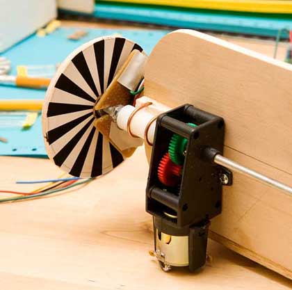
• Odometry : Track Actual wheel motion using Quad decoders.
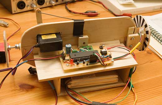
Module 1 combines:
an IMU to track the tilt of the inner pendulum and platform,
a Quad Wheel Encoder to track orb rotation and speed,
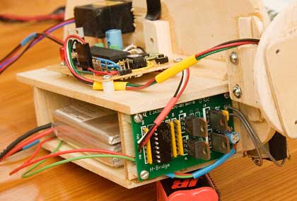
a PWM speed controller conected to an H-Bride motor control.
a 1.5ms Servo Pulse train to control an R/C servo for steering.
an I2c interface so the unit can be used as a digital slave to higher systems.
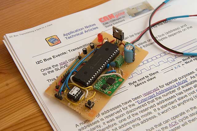
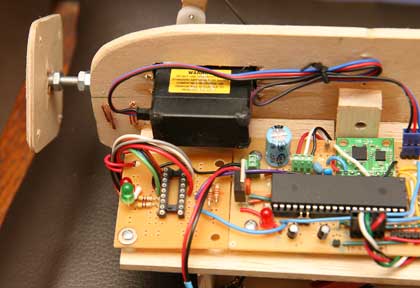
The Locomotion Module uses a PIC16F877A, a uM FPU, a Spark Fun 5DOF IMU, and has both 5volt and 3.3volt regulated supplies.
 |
|
|
 |
 |
|
|
 |
 |
|
|
 |
|
|
|
 |
Orb-Eye
Transmitter Module:
Handles button de-bounce, reading pot, setting up MiRF unit to be Txmitter, sends commands.
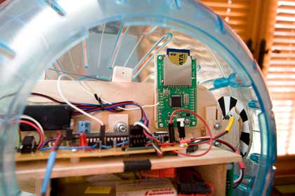
MiRF Receiver / I2c Master:
Handle interface with MiRF unit. Receive commands from Tx, sends commands down to Loco Module via I2c
Loco Module I2c Slave:
Creates 1.5ms pulse for steering servo every 20ms.
Creates 1.25 khz PWM signal for Speed Controller.
Tracks Quadrature Encoder Sensors for Orb Speed Rotation at 1.25khz sample rate.
Samples IMU measurement unit every 20ms. (5 sensors)
Integrate Gyro & Accel measurements into Swing Angle & Steering Tilt data.
Process commands comming down I2c bus so module becomes controllable slave.LocoMotion_v12.pbp
I2c_Slave_Asm.inc